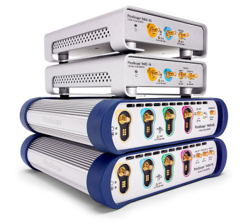
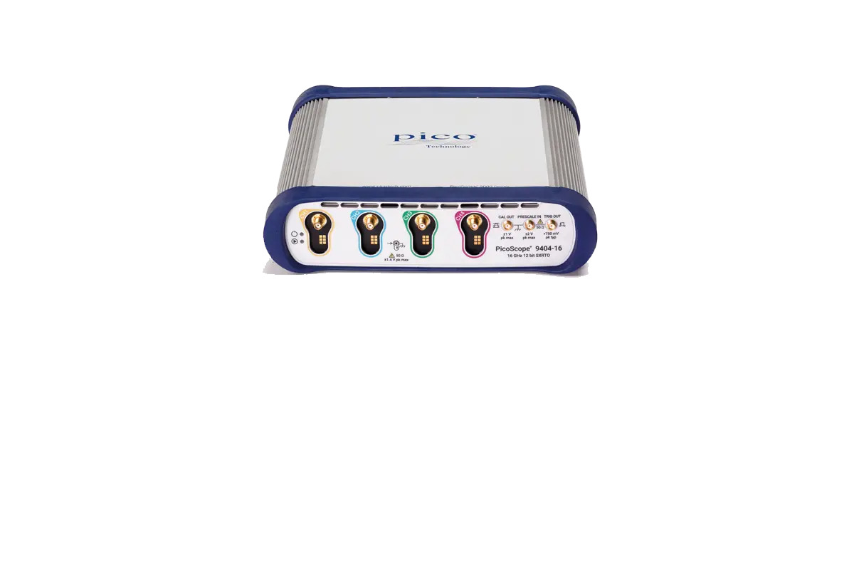
The PicoScope 9400A Series SXRTO Oscilloscopes are compact, PC-controlled high-bandwidth instruments designed for analysing repetitive analogue signals, clock streams, data eyes, fast pulses and microwave-frequency waveform behaviour.
SXRTO stands for Sampler-Extended Real-Time Oscilloscope. This architecture combines direct triggering and pre-trigger capture associated with a real-time oscilloscope with random equivalent-time sampling for much higher effective time resolution on repetitive waveforms.
The series provides:
- Four analogue input channels
- 6 GHz to 33 GHz model-dependent bandwidth
- 12-bit vertical resolution
- 500 MS/s real-time sampling
- Up to 5 TS/s random equivalent-time sampling
- Up to 250 kS shared capture memory
- 50 Ω high-bandwidth inputs
- Internal triggering from any channel
- External high-frequency trigger options
- Eye-diagram and pulse-analysis tools
- More than 200 built-in compliance masks
- Optional clock and data recovery
- USB and LAN connectivity
- PicoSample 4 software
Unlike a conventional sequential sampling oscilloscope, the PicoScope 9400A can capture signal activity before the trigger and can trigger directly from an input signal, subject to the selected model and signal frequency.
PicoScope 9400A Model Range
| Model |
Analogue Channels |
Analogue Bandwidth |
Maximum Effective Sampling |
| PicoScope 9404A-06 |
4 |
6 GHz |
1 TS/s |
| PicoScope 9404A-16 |
4 |
16 GHz |
2.5 TS/s |
| PicoScope 9404A-25 |
4 |
25 GHz |
5 TS/s |
| PicoScope 9404A-33 |
4 |
33 GHz |
5 TS/s |
All models provide 12-bit vertical resolution and four analogue channels. The selected model determines bandwidth, effective timing resolution, input connector type and high-frequency external trigger capability.
Up to 33 GHz Analogue Bandwidth
The highest-performance model, the PicoScope 9404A-33, provides DC to 33 GHz analogue bandwidth.
Available bandwidth configurations include:
- 6 GHz
- 16 GHz
- 25 GHz
- 33 GHz
Typical full-bandwidth transition times include approximately:
- 58.3 ps for the 6 GHz model
- 21.9 ps for the 16 GHz model
- 14 ps for the 25 GHz model
- 10.6 ps for the 33 GHz model
These bandwidth options support measurement of:
- High-speed serial data
- Microwave pulses
- Fast clock signals
- Optical receiver outputs
- Semiconductor switching behaviour
- Radar signals
- Telecom interfaces
- Picosecond pulse transitions
- Signal-integrity problems
- RZ, NRZ and PAM4 data eyes
The required bandwidth should be selected according to the fastest transition, pulse width and interface data rate being evaluated.
Four 12-Bit Analogue Channels
Every PicoScope 9400A model provides four analogue input channels with 12-bit vertical resolution.
A 12-bit acquisition system provides 4,096 quantisation levels, allowing significantly greater amplitude detail than a standard 8-bit oscilloscope.
The four-channel architecture supports:
- Differential signal-pair comparison
- Clock and data analysis
- Transmitter and receiver comparison
- Multi-lane serial interface testing
- Input and output pulse measurements
- Timing correlation across several signals
- Multi-channel eye-diagram analysis
- Phase and delay measurements
- Pulse response comparison
- Simultaneous monitoring of several RF paths
The 12-bit resolution is maintained across the instrument bandwidth and is not reduced when additional channels are enabled.
Sampler-Extended Real-Time Architecture
The PicoScope 9400A Series uses a sampler-extended real-time architecture rather than conventional high-speed real-time acquisition alone.
In real-time mode, the instrument samples at up to 500 MS/s. For repetitive signals, random sampling combines samples collected across multiple trigger events to create a waveform with much finer effective time spacing.
This architecture provides:
- Direct triggering from the measured input
- Pre-trigger waveform capture
- Post-trigger waveform capture
- Random equivalent-time sampling
- High effective timing resolution
- Better visualisation of repetitive high-frequency signals
- Faster setup than many traditional sequential sampling systems
Random sampling is intended for repetitive signals whose waveform shape remains stable around the trigger point. It should not be presented as a method for capturing an isolated 33 GHz single-shot event.
Up to 5 TS/s Effective Sampling Rate
Maximum random equivalent-time sampling depends on the selected model:
- 1 TS/s on the 6 GHz model
- 2.5 TS/s on the 16 GHz model
- 5 TS/s on the 25 GHz model
- 5 TS/s on the 33 GHz model
The 5 TS/s effective rate provides timing placement resolution down to approximately 0.2 ps.
The effective rate helps represent:
- Picosecond waveform transitions
- High-speed clock edges
- Microwave pulses
- Fast serial data eyes
- Pulse overshoot and ringing
- Jitter-related waveform spread
- Inter-symbol interference
- Small timing variations
The page must distinguish the 500 MS/s real-time sampling rate from the up to 5 TS/s random equivalent-time rate.
500 MS/s Real-Time Sampling
The PicoScope 9400A Series provides a real-time sampling rate of 500 MS/s.
Real-time acquisition is useful for:
- Lower-frequency non-repetitive events
- Trigger setup
- General waveform observation
- Pre-trigger and post-trigger analysis
- Slow control and envelope behaviour
- Roll-mode acquisition
At very high input frequencies, the instrument relies on random equivalent-time sampling to reconstruct repetitive waveform detail.
The real-time sample rate remains available regardless of the number of enabled channels, although capture memory is shared among active channels.
Up to 250 kS Shared Memory
The PicoScope 9400A Series provides up to 250 kS capture memory, shared between enabled analogue channels.
The memory supports:
- Real-time acquisition
- Random sampling
- Roll-mode capture
- Pre-trigger observation
- Post-trigger observation
- Segmented acquisition
- Pulse and eye analysis
- Measurement statistics
This memory depth is considerably smaller than the gigasample memory found in some general-purpose real-time oscilloscopes. The primary strengths of the PicoScope 9400A are bandwidth, timing resolution, trigger precision and repetitive-signal analysis rather than long-duration high-rate recording.
Segmented Acquisition
Segmented acquisition divides the available waveform memory into multiple individual captures.
The PicoScope 9400A supports up to 1,024 waveform segments.
Segmented acquisition is useful for:
- Rare pulse events
- Repetitive packet captures
- Intermittent anomalies
- Pulse-to-pulse comparison
- Manufacturing tests
- Radar pulse analysis
- Unusual eye-diagram events
Captured segments can be overlaid or examined individually. Segment-search functions help locate anomalous traces within a large group of captures.
Direct and External Triggering
The instrument includes an internal trigger system on every analogue channel.
Trigger options include:
- Direct triggering from an analogue input
- External direct triggering
- Prescaled high-frequency external triggering
- Optional recovered-clock triggering
- Pre-trigger and post-trigger acquisition
- Trigger output for synchronising external instruments
The direct trigger system supports signals up to approximately 2.5 GHz from an input channel, while an external direct trigger path extends to 6 GHz.
On higher-bandwidth models, the prescaled trigger input supports:
- Up to 16 GHz on the 9404A-16
- Up to 20 GHz on the 9404A-25
- Up to 20 GHz on the 9404A-33
This allows stable acquisition of high-frequency repetitive signals where direct internal triggering is insufficient.
Low Trigger Jitter
The trigger architecture provides typical trigger jitter as low as approximately:
Low trigger jitter is important for:
- Eye-diagram clarity
- Rise-time measurement
- Pulse-width characterisation
- Clock-jitter analysis
- Phase measurements
- Serial data validation
- Repetitive pulse alignment
- Timing-distribution analysis
Lower trigger uncertainty reduces waveform smearing when many repetitive acquisitions are combined.
Eye-Diagram Analysis
PicoSample 4 includes tools for generating and measuring eye diagrams.
Supported signal formats include:
Eye-diagram analysis can be used to evaluate:
- Eye height
- Eye width
- Crossing percentage
- Noise
- Jitter
- Extinction behaviour
- Overshoot
- Rise and fall time
- Inter-symbol interference
- Signal margin
The software provides more than 130 eye-diagram measurement parameters and can apply statistical analysis across repeated acquisitions.
More Than 200 Compliance Masks
PicoSample 4 includes more than 200 built-in mask tests for common high-speed standards.
Applications include:
- Ethernet
- Fibre Channel
- SONET and SDH
- USB
- InfiniBand
- XAUI
- Telecom interfaces
- Optical communication systems
- User-defined signal standards
Users can also create custom masks for application-specific limits.
Mask testing helps:
- Validate transmitter performance
- Identify waveform violations
- Compare signals with standards
- Perform manufacturing checks
- Assess signal margin
- Locate intermittent data-eye failures
The PicoSample 4 mask and measurement features are included without separate software licence charges.
Optional Clock and Data Recovery
Clock and data recovery is available as a factory-fitted option.
The CDR module can recover the clock from an incoming serial data stream and use it as the oscilloscope trigger.
Supported maximum data rates are approximately:
- 5 Gb/s for the 6 GHz model
- 8 Gb/s for the 16 GHz model
- 11.3 Gb/s for the 25 GHz model
- 11.3 Gb/s for the 33 GHz model
The recovered clock and data are also available through rear-panel SMA outputs.
Clock recovery is useful for:
- Serial links without a separate clock
- Receiver-oriented eye analysis
- Transceiver validation
- Jitter testing
- Telecom interface characterisation
- Triggering additional test equipment
The CDR option is not standard and should be clearly described as factory-fitted and optional.
Pulse and Impulse Measurement
The PicoScope 9400A Series is designed for measuring extremely short transitions and pulses.
Depending on model, it can analyse:
- Step transitions down to approximately 10.6 ps
- Impulses down to approximately 22 ps
- Repetitive fast laser pulses
- Radar pulses
- Semiconductor switching events
- Microwave pulse responses
- Optical-to-electrical converter outputs
- High-speed clock transitions
These capabilities make the series useful in research areas where a conventional lower-bandwidth oscilloscope would substantially alter or obscure the measured waveform.
Automatic Measurements
PicoSample 4 provides extensive automatic measurement tools.
The software includes:
- More than 40 pulse and waveform measurements
- More than 70 general measurement parameters
- More than 130 eye-diagram parameters
- Up to ten simultaneous measurements
- Measurement statistics
- Gated measurements
- Marker measurements
- Trend plots
- Histograms
Measurements can be applied to the complete waveform or restricted to selected regions using measurement gates.
Waveform Mathematics
PicoSample 4 provides more than 50 built-in mathematical functions.
Analysis capabilities include:
- Addition
- Subtraction
- Multiplication
- Division
- Differentiation
- Integration
- FFT
- Filtering
- Averaging
- Trend functions
- Custom mathematical expressions
- Channel-to-channel calculations
Maths functions are useful for differential calculations, pulse analysis, frequency-domain investigation and custom signal processing.
FFT and Frequency-Domain Analysis
The software provides FFT-based frequency-domain analysis for repetitive high-speed signals.
Applications include:
- Harmonic analysis
- Clock spectrum measurement
- Pulse spectrum analysis
- RF signal investigation
- Noise identification
- Oscillation detection
- Microwave system testing
- Telecom signal evaluation
The 9400A is primarily an oscilloscope and timing-analysis platform. A dedicated spectrum analyser may still be required for measurements needing calibrated RF power, very wide dynamic range or specialised modulation analysis.
PicoSample 4 Software
PicoSample 4 provides the user interface for controlling the PicoScope 9400A.
The software supports:
- Touchscreen or mouse operation
- Resizable waveform displays
- Multiple waveform grids
- Up to four independent zoom views
- Eye-diagram measurements
- Mask testing
- Pulse measurements
- Histograms
- Trend analysis
- Mathematical channels
- Save and recall configurations
- Measurement statistics
- Segmented acquisition
- Automated control
All core PicoSample 4 software features and updates are included with the instrument without separate feature licences.
USB and LAN Connectivity
The PicoScope 9400A Series supports:
- USB connection
- LAN connection
- Remote software operation
- Automated control
- Multi-instrument operation
- Trigger output
- Optional recovered clock and data outputs
The instrument normally connects to a computer through USB. When configured for network use, PicoSample 4 can address up to eight PicoScope 9400A instruments through LAN connections.
This supports:
- Multi-channel research systems
- Remote laboratories
- Automated validation
- Production testing
- Synchronous test setups
- Distributed measurement systems
Applications
The PicoScope 9400A Series is suitable for:
- High-speed digital design
- Signal-integrity analysis
- Telecom testing
- Microwave pulse measurement
- Optical communication testing
- Data-eye analysis
- NRZ and PAM4 testing
- Semiconductor research
- Radar development
- Laser pulse characterisation
- Clock and timing analysis
- Jitter measurement
- Transceiver validation
- High-energy physics
- Manufacturing validation
- Research laboratory testing
- Service and repair of high-speed systems